![]()
Final Assembly 2008
139" Turbo Orca
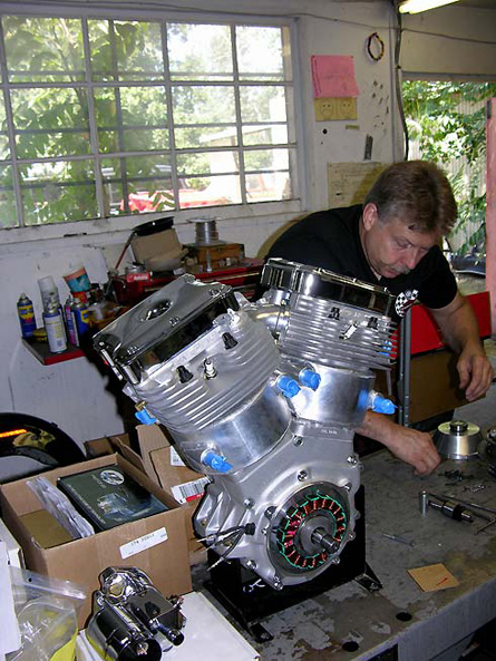
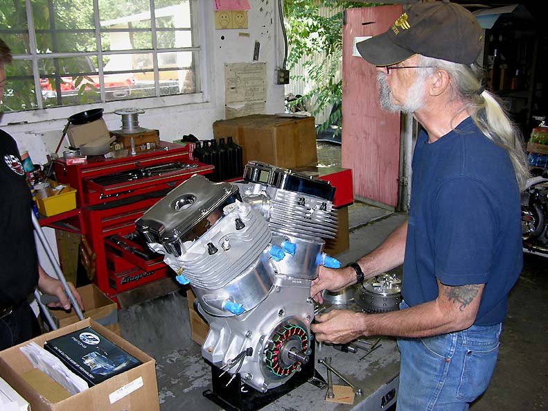
Carl Pelletier of Competition Motorcycles did the final assembly of the 139" Orca Turbo engine. Carl has been building race engines for over 20 years and was the best man for the job. He'd rather work on Top Fuel Nitro burning engines as they "make more noise", but he squeezed the 139" Orca into his busy schedule. Carl used all the tricks in his playbook to get the right rods, bearings, clearances, balance factors as well as some secret stuff from his world of Pro Dragsters, Pro Fuel and Top Fuel experience to assemble the engine.
This engine is a bit different as it takes a lot of specialists to bring this project together. No one person can do it all. People like John O'Keefe of Branch O'Keefe who ported the S&S SA B2 cylinder heads. RB Racing who designed the specialized components like the water-cooled cylinders and the basic architecture of the engine. Then there are a myriad of suppliers like CP pistons, A1 Technologies, Ferrea Valves and many others. S&S Cycle's racing department suppied the raw B2 head castings and machined the cases to RB Racing's custom patterns.
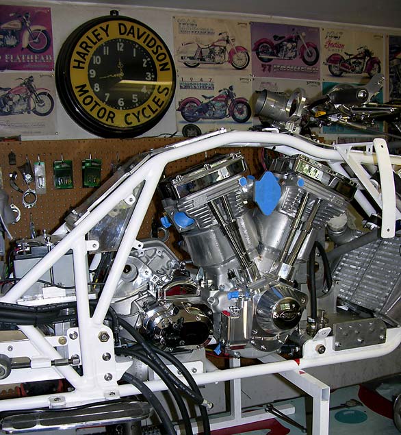
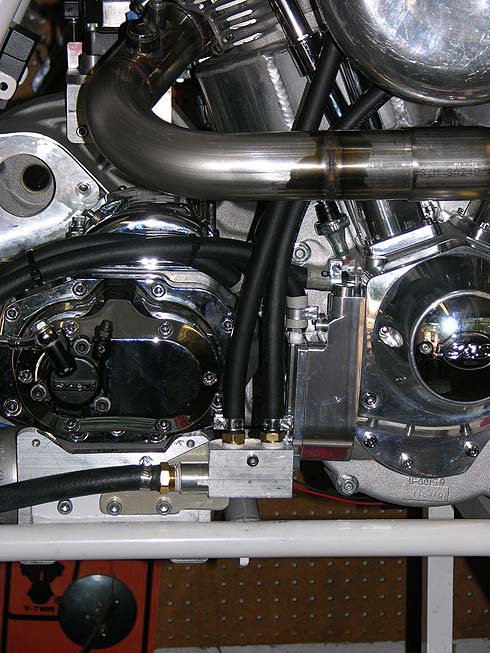
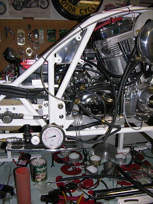
Here the engine finds its home in the Bullett's frame. The blue tape keeps dust, stray debris, and critters out of the engine. Once in the assembly phase it is no longer in a clean engine assembly room. Only Mike knows what all the hoses are. We won't show you the radiator hoses as they are hidden behind the radiator. They would scare you if you saw them anyway.
Billet Wet Primary with Dry Clutch
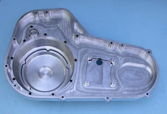
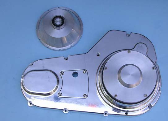
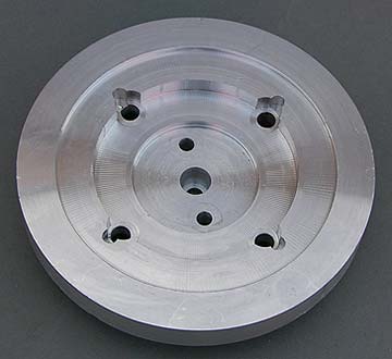
If you followed the development of the Bullett's clutch on the Bonneville 2 web page this is the final rendition after Carl removed the chunks of 6061-T6 from his lathe and mill. The Barnett Billet FXR Primary cover has been modified to accept an outboard support bearing and the clutch basket is sealed from the oil lubricating the primary chain by the machined "hub-cap".
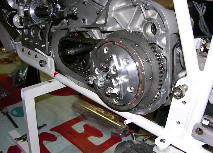
Here you can see the lock-up mechanism that will be hidden behind the machined clutch "hub-cap". The narrow chain drive primary is necessary to reduce frontal area. The sintered iron, dry lock-up clutch is necessary to hold the turbo horsepower under full boost on long course. Unlike dragsters we will not be using the clutch as a slipper mechanism. Next step, get it all aligned.
Whadda you mean I can't get there from here?
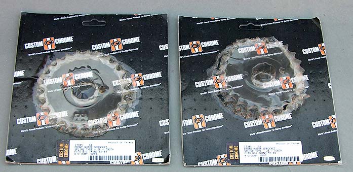
The Bullett is not a catalog bike so you just can't order parts, bolt it all together and then head for the rider's sky box where shrimp cocktails, long legged things and big leather chairs await. The Bullett uses a late style FXR primary, a custom sintered iron clutch, and none of this lines up with any known primary sprocket location. Since we are using a 1955 to 1984 non-compensating 24 tooth sprocket you get to take two of these to make one new one. Go to your local Harley dealer and ask for a 24 tooth 1955 sprocket and they will drag you over to the clothing section to spruce you up a bit before they lead you to that new chrome-laden, accessorized 110" CVO scooter. You are not going to get those sprockets. They don't let Shovelheads, Panheads or much less Evos in the doors anymore.
Thank Taiwan and Custom Chrome for providing the raw material. They may be heading for oblivion in this brave new world order, but two more sales are all we need for the Bullett.
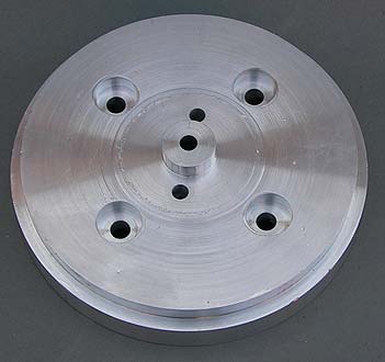
How do you hold and machine two case hardened sprockets? Well, you could grab that spare mainshaft but that would be too easy. Then there is the question of cutting out the middle of one of the sprockets. Hey, a lathe and a chunk of aluminum left over from the jackshaft machining was sitting there asking to go to Bonneville. What the hell.
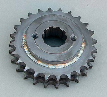
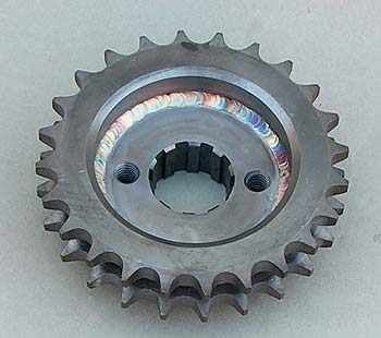
.390" offset, 24 tooth, non-compensating sprocket. Just slice open the shrink wrap and put it on the bike. Don't think Willie G had one or we would have asked.
Jim's Fat5 Trans modified for Hydraulic Actuation
![]()
If you followed the machining of the Jim's transmission cover on the Bonneville 2 page here is the unit installed in the Bullett. Mike made a special long hydraulic hose from his handlebar master cylinder. Without hydraulics you would not be able to easily actuate the clutch. After the unit was installed Mike made a longer clutch pusher rod out of 5/16" drill rod and heat treated the pusher ends after machining by heating and quenching the tips.
High Stakes
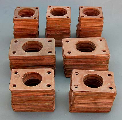
You're sitting at the Baccarat table in Wendover keeping your steely eyes on the Mormons who've sneaked over from Salt Lake to be naughty, and those Bonneville groupies who are eyeing your pile of chips see a good time coming. Push that pile of water jet cut copper gaskets out and bet the farm. It's your lucky night.
Vacuum Ports
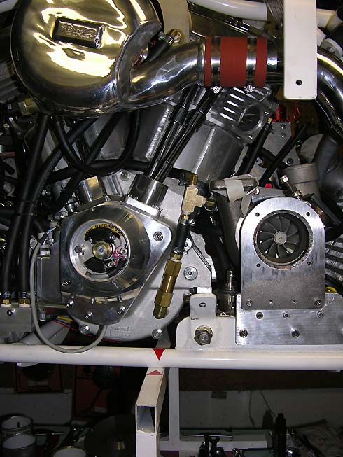
Mike machined a vacuum distribution block that runs to the GZ Motorsports Gilmer Belt driven vacuum pump. The vacuum pump is driven off of the Bullet's jackshaft and provides positive evacuation of both the upper end and lower end of the 139" Orca motor. These are antique motors originally intended for bicycle frames and the oil and ventillation systems weren't designed for the long course at Bonneville under full boost.
Upper End Oil Scavenge
In addition to the vacuum (air/oil mist) scavenging of the upper and lower ends we are also using secondary oil scavenging of the upper end. Carl Pelletier machined in extra ports and we are using the crankcase pulsations to pull extra oil out of the upper end. Too much oil can cause issues on the long course and excess oil can find it's way past guide seals and into the combustion chamber where it will lower the octane of the mixture leading to detonation and piston failure.
There is no space!!!
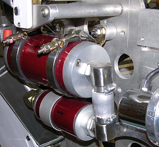
Special stainless steel couplings had to be designed to flow the fuel between the filter and the fuel pump as the electric shift mechanism butted directly up against the fuel components.
Rules, Rules, Rules
The rule book mandates that all fuel lines be covered in some form of fire protection. We used XRP fire wrap to cover all the fuel lines, even the little short one between the fuel filter and the fuel pump. It can be a real bitch to install if you order one size too small, or even if you order the "correct, recommended, size".
Boost Control, Kill switch, and mysterious red switch
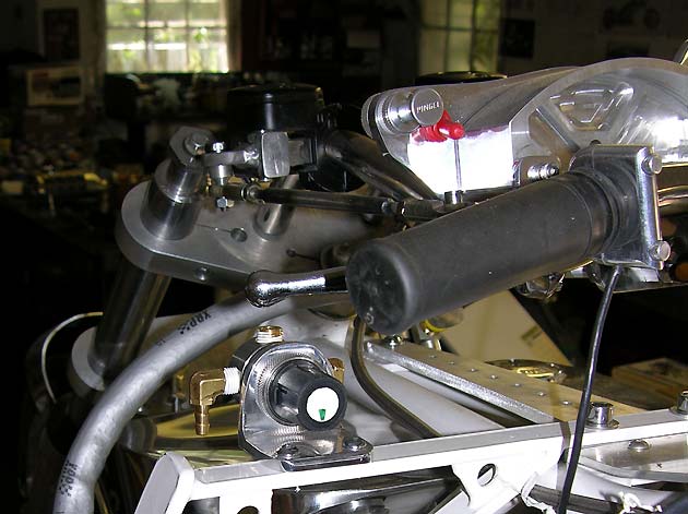
Our stainless steel boost controller, 5-25 psi, with green arrow marking the fully open position. Pingel kill switch, tehered to Mike, in case of rider separation. Mysterious red switch for unknown purposes.
Electronics
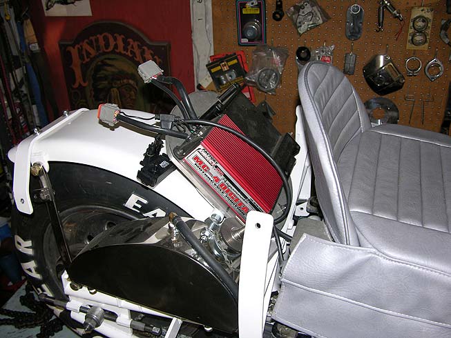
Hidden behind Mike's seat is the MSD MC-4 Ignition and the RSR Fuel Injection ECU. The polished stainless steel saddle tank holds the Brad-Penn engine oil. Mike set the bike up for both the MSD MC-4 and the MSD Pulse Ignition system with the mounting plate having two sets of holes for the different size units.
We will run the MSD MC-4 Ignition first as it is programmable in respect to advance curves both normally aspirated and and under boost . The MSD Pulse Ignition serves as a backup and uses a series of dip switches to set ignition's parameters. The MC-4 requires that you manually set a specific advance with a degree wheel off of the crankshaft, then use software to put in various levels of retard. The MSD Pulse Ignition only requires you locate TDC on the compression stroke of the front cylinder. Both systems willbe firing four spark plugs through a Bosch Motorsport coil.
Gauge Panels w/ Racing Holes
New pressure and temperatures gauges are being prepared for the Bullett. In as much as they are a 2" format round gauge, center back mount, Mike prepared ventillated flat surfaces with holes to accept the 5/16" x 18 gauge mounting bolts. The gauges have memory and warning functions and will auto-dim. They are to be wired into a separate switched 12V circuit so they will retain their memory when the bike is shut down.
Orca Turbo Dash
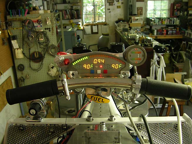
0-3 Bar Billet Dash with memory. Red l.e.d. indicates there is no oil pressure. Dual O2 Gauge has two additional l.e.d.s that will show when each stage of the water injection is activated.
Mysterious red switch resides at the left, it's function only known to Mike. Do not touch the red switch.
Mike's Throne or Front Row Seat
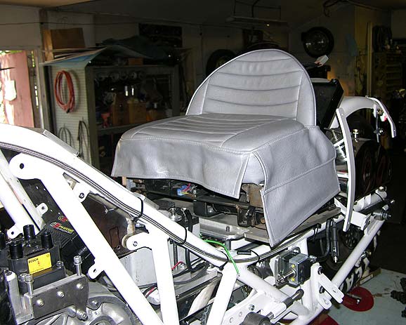
Electrically powered to move front and aft, this is the best seat in the house. A great white expanse defined by a few dark lines and mile markers. For some it is a dream and for others it is a reality. Reality can, however, be a bitch. As they say, no suffering, no art.
Final assembly, then testing
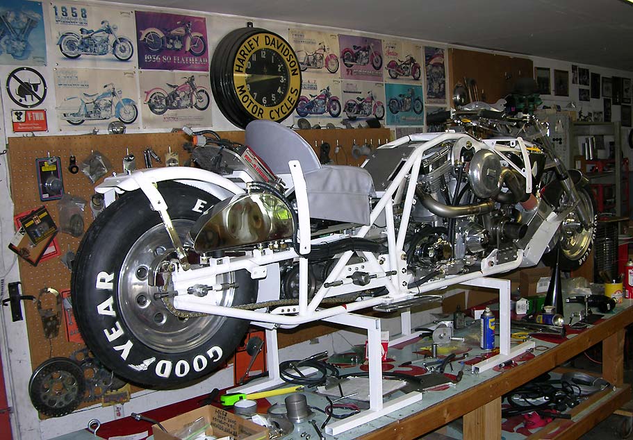
You have to finish the inside before you can put on the polished aluminum skin. Hardware stores, hydraulic supply houses, fitting manufacturers and an myriad of industries are being held North of a recession by the Bullett. Hose clamp factories have put on second shifts to keep up with the Bullett's demands. 99" of wheelbase barely seems enough to fit all of the components.
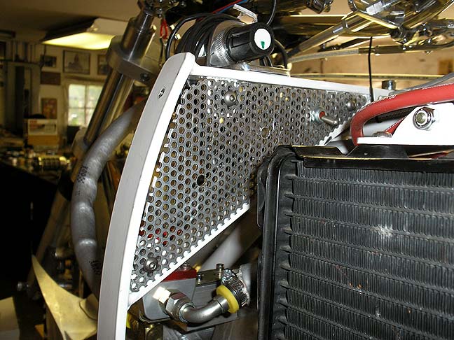
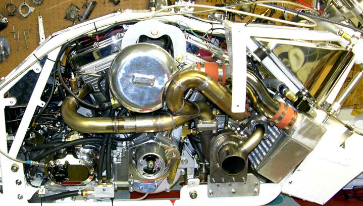
Intercooler Tubes
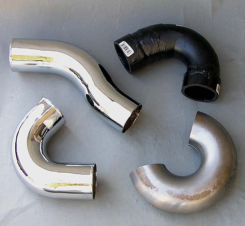
To prototype the turbo to intercooler and intercooler to plenum 2.5" diameter tubes you first have to stop at the local plumbing supply house and pick up some plastic pipe and pipe cement. The upper left chrome tube which goes from the intercooler discharge to the inlet plenum is easy...just fab it in 18 gauge, make a fixture then make the final part in 16 gauge tubing and have it chromed, first removing any weld seams. We hate weld seams, except on the stainless headers which we leave alone.
The chrome tube to the lower left is the turbo discharge to intercooler inlet which is way, way in the Bullet's bowels. We took some plastic pipe and glued it together and then made a fixture and replicated the part in 16 gauge steel with a tight radius 2.5" "donut" from Road Race Engineering. Weld it up, remove the seams and get the part chromed.
8228
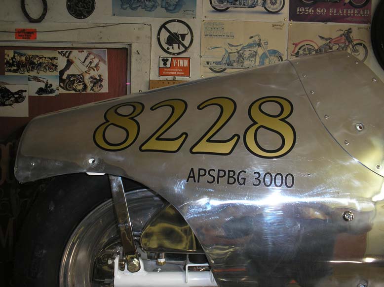
The tail section in place, it's time for the SCTA-BNI approved "8228" graphics. Mike called out the design and a local Boise graphic artist executed the gold and black letters and came over to apply them herself and to see "a Bonneville bike" because she had seen the movie "The World's Fastest Indian" starring Sir Anthony Hopkins.
Water Injection
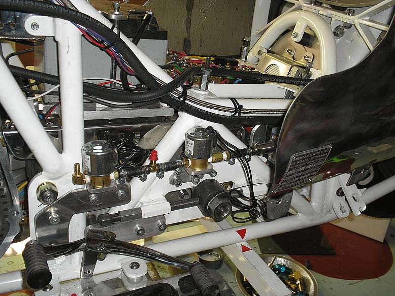
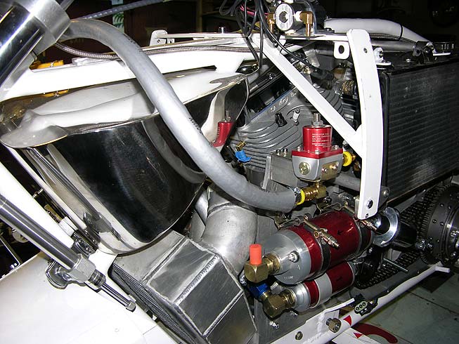
Initial running will be with a two stage water injection system with two 120cc nozzles, one in the inlet manifold and one in the inlet plenum. Normally we'd run one 240cc nozzle and activate it at a higher pressure but most initial running will be at low boost levels so we feel safer with less water earlier, in a staged manner. When we run higher pressures we'll switch to a two pump system and spray the intercooler with a second 240cc nozzle.
Two solenoids are used to activate the primary and secondary nozzles.
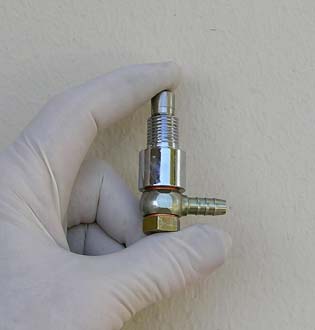
This is a banjo bolt 120cc water injection nozzle we machined for the Bullett's intake manifold. It will activate at a low boost pressure. It threads into the floor of the inlet manifold.
Inlet Plenum
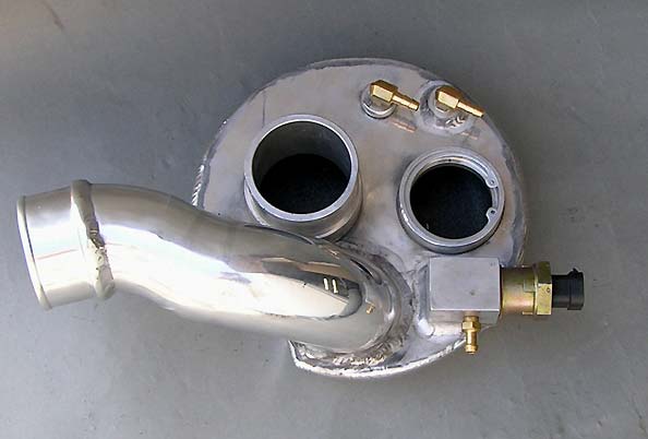
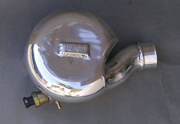
The upper right brass fitting is the secondary 120cc water injector nozzle which will activate at a higher boost pressure. To it's left is the "boost-only" signal that will activate both primary and secondary nozzles. The square block is the idle air control motor controlled by the RSR Fuel Injection ECU. The snap ring cavity holds a dual function inlet breather and closed throttle boost relief valve.
Here we are using controlled air pressure to set the switches for the two water injection nozzles. The nozzle in the inlet manifold activates at 6 psi and the the nozzle in the plenum activates at 10 psi.
It Barks
Goldilocks came in, ate the porridge and hit the starter button. The Salt Bears ate her ass. No water or oil puddles but she left her gold tint on the stainless manifold. Her fingerprints were found on the red switch. No mercy. See the Bullett's maiden voyage to the Bonneville Salt Flats.