Pectel SQ6 Wiring Loom Construction
Here is an owner / private construction of a wiring harness for an 88 pin
Cosworth Pectel SQ6 ECU, minus a number of steps like crimping
about 200
pins and sockets, and assembling Deutsch Autosport and SQ6 88-pin
connectors...as well as installing the DR25 shrink tubing and molded
transitions. When you look at the planning and complexity you might
well consider letting a professional do the work for you. Tools, supplies, labor and experience all have to be present.
In this case the MIL-W-22759 Spec 55 wiring is all white which complicates both assembly, maintenance and repair issues.
Wiring Harness Begins
You start with (as usual) a mock up loom in order to determine the
correct lengths for everything and also the placement of the various
sensors on the car and engine:
This uses some old wire and connectors and is then laid out on a board
/ flat surface. Then having marked everything out you lay down the actual
wires as they will be in the loom where they need to go.
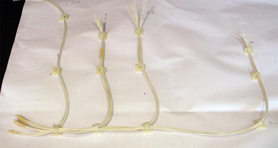
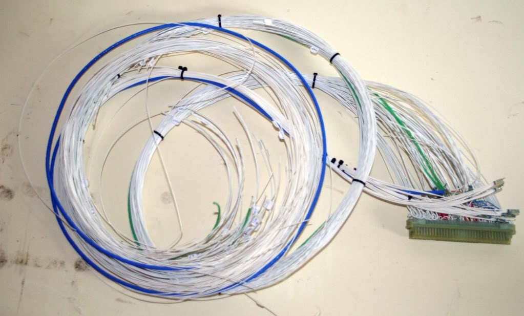
Unfortunately I missed quite a few stages out when it came to taking
pictures, basically the wires you see above are all twisted together
which gives the loom a neat round shape and allows it to bend freely
without losing its shape. I have decided to use filler wires mixed in
with the actual loom in order to keep the shape neat at the expense of
a little weight increase.
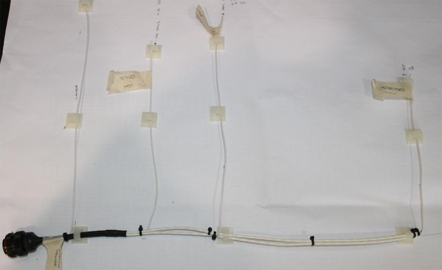
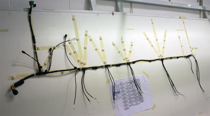
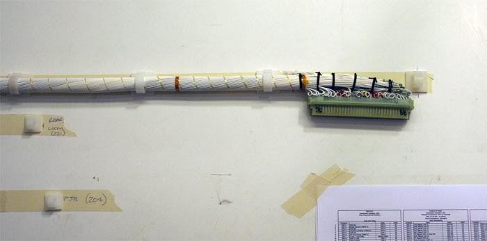
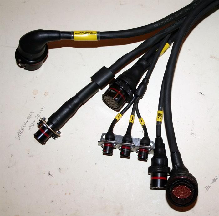
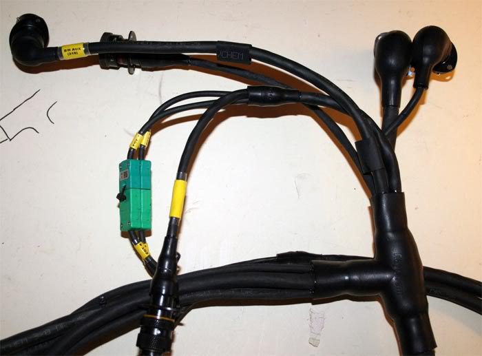
The loom shown is is the "Power" loom part of the ECU, I have kept the
higher current and potentially noisy part of the loom separate from the
"Data" side of the loom. From left to right. The large connector plugs
in to the bulkhead to connect to the ECU inside the car. Then there is
the Lambda, the 4 Ignition coil wiring, the Engine grounds and then the
Injectors.
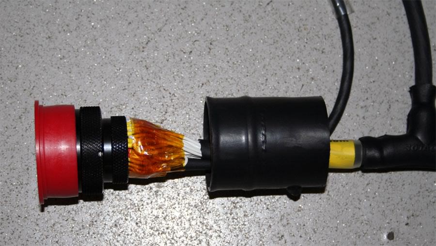
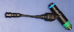
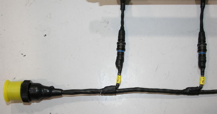
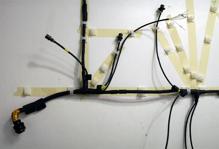
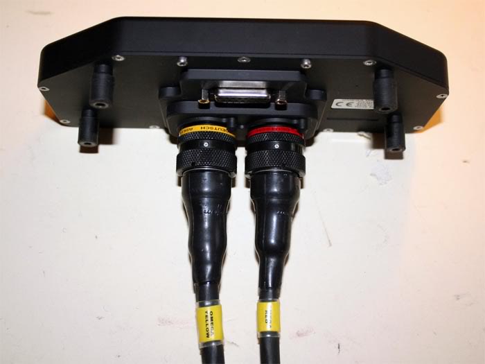
The above shows the Deutsch Autosport connector before the boot (the large black
hoop) is shrunk down on to the connector. The wires have service loops
in them which is basically a 'pig tail' which gives a bit of spare wire
if there is ever a need for a repair and this is covered with polymide
tape to protect it and stop any of the 'glue' which seals the boots
from sticking to the wires.
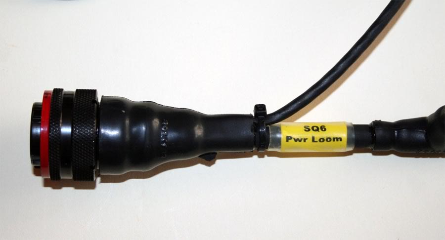
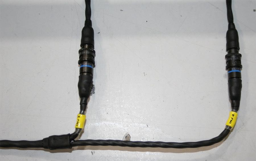
This shows the same connector but with the boot shrunk down (The Ty-wrap is just to hold it together while the 'glue' dries.
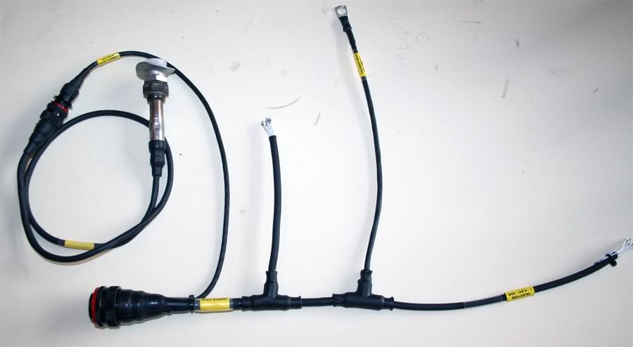
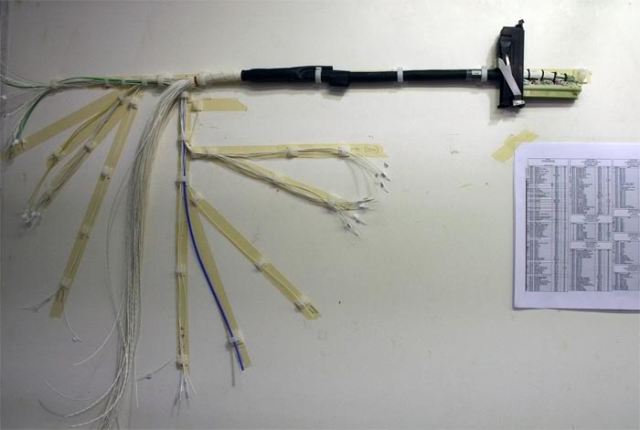
Here is the near complete loom with the NTK Lambda plugged in to check
lengths on the car. Heat shrink labels and clear Kynar shrink over the
labels.
It's important that the ECU earths directly to the engine to minimize any noise or "ground loops"

I am using a mixture of both Spec 55A and 55M wire as 55M is not
available in gauges above 20 swg. I am also using both standard DR25
and DR25 TW (Thin Wall) heat shrink tubing.
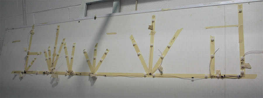
This is the mock up loom laid on the board ready to start building
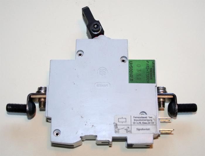
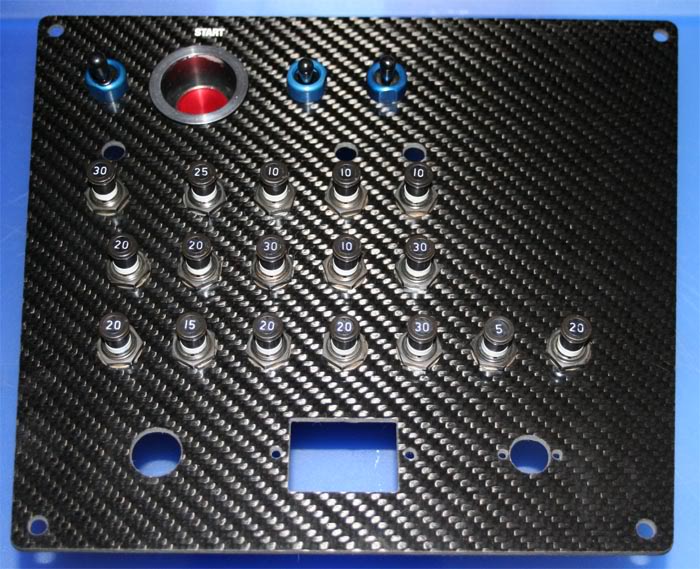
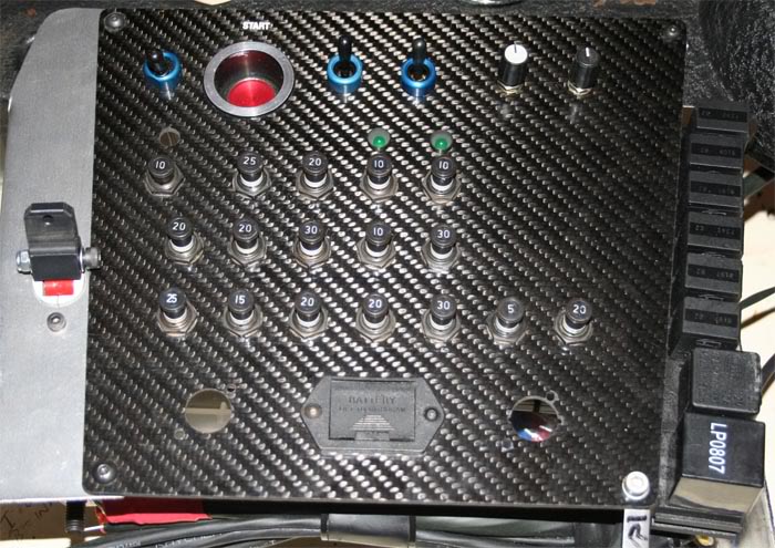
Also got my master switch, it is an ETA switch, and can be triggered
remotely by another electrical 'kill' switch. The main contacts have
been modified to take battery cable sized connections.
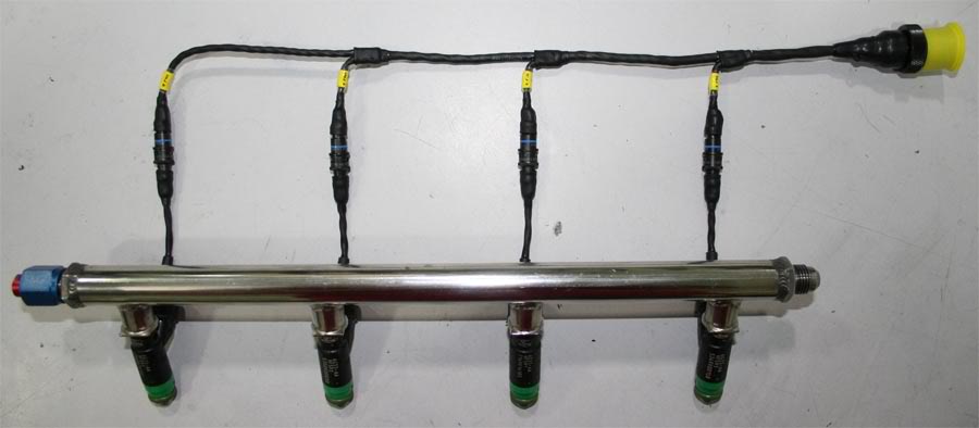
And the injector loom is now finished:
Basically the 'flying lead' has been 'potted' in to the injector and
then had a Raychem boot fitted over it so the only removable connector
is the mini Deutsch type connector you see.
These injectors are off an Aston Martin and the standard connectors are
not properly sealed from moisture (not to mention the fact that I
didn't have any!) hence I converted them to connectors that I did have,
its reasonably common in Motorsport when OEM type sensors are used that
don't have properly sealed connectors.
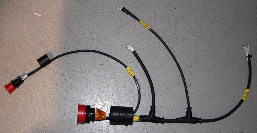
The Engine loom is all but finished:
This was before I finally took it off the board to put the Raychem boots on and fit the sensor sockets that I could.
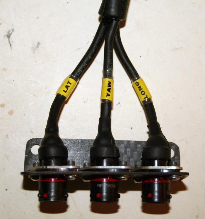
Each sensor connection on to this main loom has exactly the same socket
which has, 5V, 12V, Analogue GND, Digital GND and signal which
basically gives me the freedom to plug pretty well any sensor into any
point on the loom and then alter the SQ6 setup to suit.
In order to do this every sensor has to have the same connection (opposite gender to the loom) on it as well.
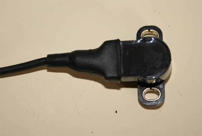
This is the std GSXR ITB TPS and its connector:
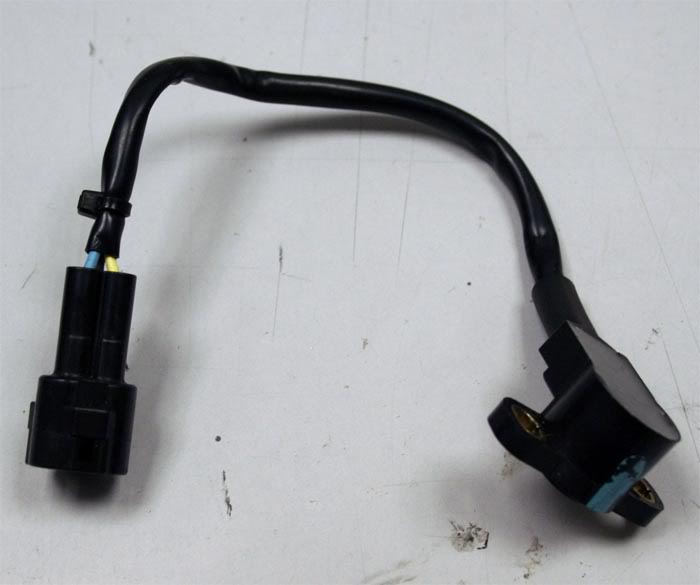
It's connector is not properly sealed from fluids and has a loose plastic outer covering to protect the wires.
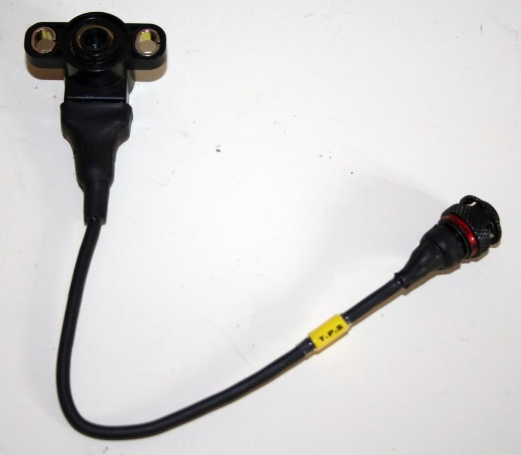
First stage is to remove the original wiring and using Raychem crimp splices fit Spec55 wires to it:
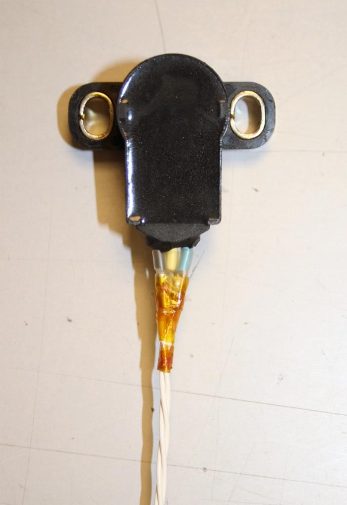
The boot and DR25 heat shrink are now fitted, the booted is injected
with 'potting' compound which basically seals the sensor end.
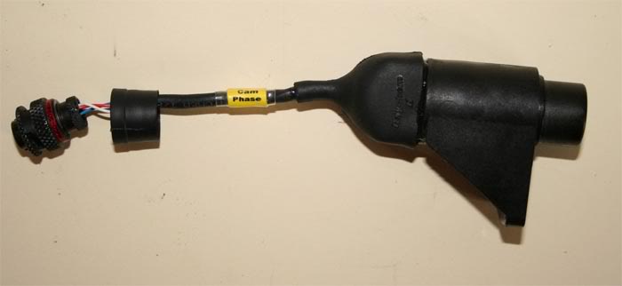
The same done to the Cam phase sensor, just needs the boot shrinking and sealing:
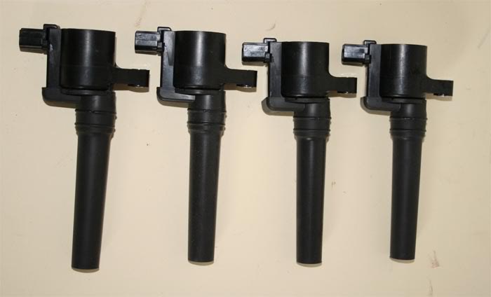
Got hold of some COP's which I will experiment with, the engine loom is
made to use both wasted and individual coil on plug units:
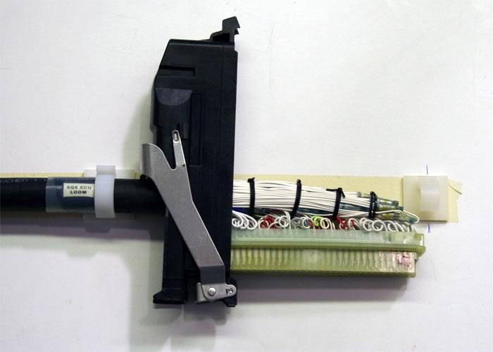
One job I haven't been looking forward to is the ECU loom, mainly due to the 88 way AMP connector that mates to the SQ6.
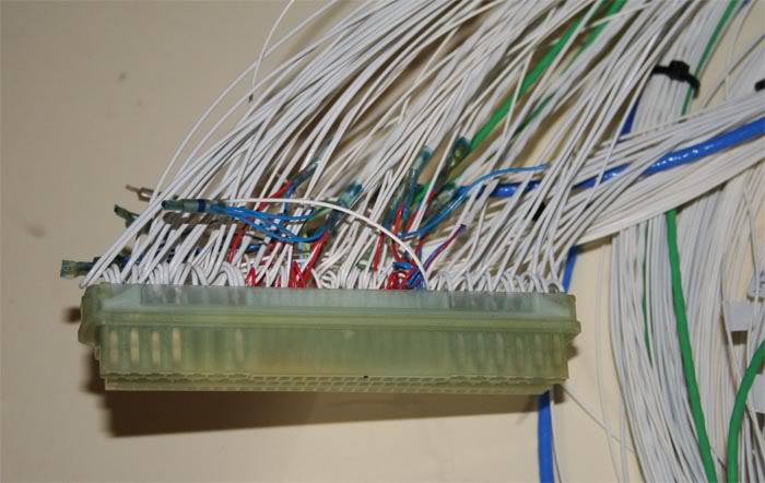
This is part way through showing the service loops, splices and screen
drain splices. It gets very busy in the connector as the wires are
added especially when trying to add service loops.
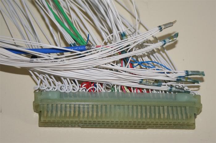
And the rats nest it all looks like at the moment:
Did some more on the ECU loom, its less of a rats nest now. The first
leg of the loom has been twisted and bound with kevlar tape to hold its
shape before covering in DR25 TW.
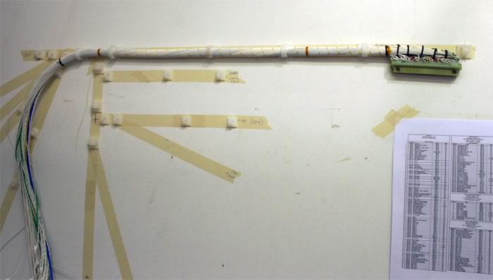
The wires in the back of the 88 way connector have been tied with 'boot
lace' to hold its shape before the cover is put on. Starting to cover
the first leg of the loom before progressing on to the rest.
I will finish the rest of the loom legs tomorrow as regards putting the
correct wires in them but it is taking a while as I am continuity
testing as I go to check each wire is correct.
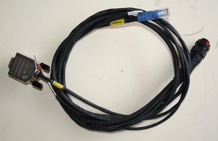
A little boring but this is the Comms lead I will use for the SQ6 and the Omega dash (Ethernet, RS232 and CAN):
Part of my Omega dash loom;
The 'In car' ECU loom;
Some of the In car sensor connections from the ECU loom;
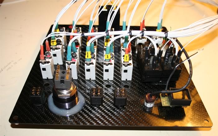
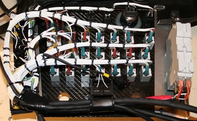
Done a little more on the PJB which is now all but finished:
Part of the process was marrying the Omega dash loom to the PJB and I
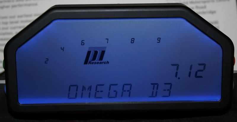
couldn't resist having a play, this is the Omega in demo mode: Power up
page:
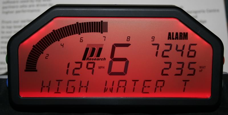
Alarm mode:
And a typical display page:
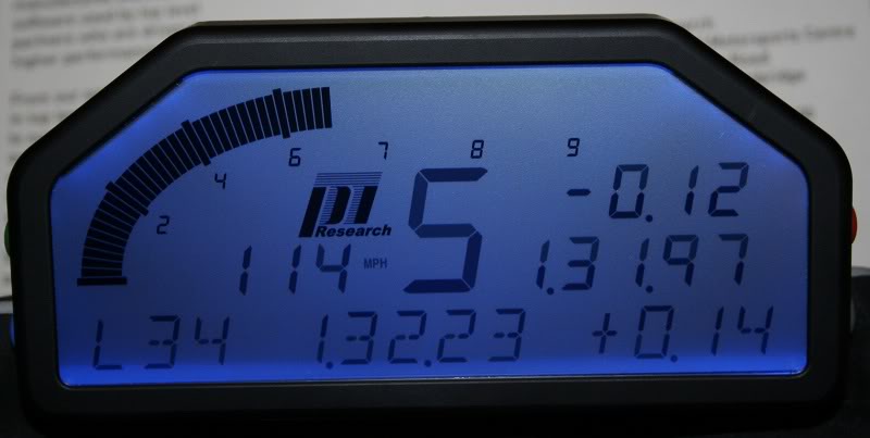
In reality this only proves out a few wires but it feels like its coming together seeing bits like this powered up.
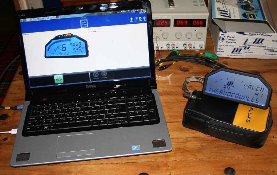
Progressing slowly with my Omega dash learning:
Managed to connect an EGT and then via the 'Watch channels' options
watched the temperature change to confirm both of the thermocouple
channels are correctly wired / working. I did the same with the
internal accelerometer watching the output on the dash
Currently setting it up to manually log and download this data with
toolset on the PC shown, also confirming the ethernet aspect of the
download works. Once this is done I want to connect the SQ6 and make
sure the Omega can read in the data from it.