Advanced Engine Management: CalTool 3.6 Pectel SQ6M, Fly-By-Wire


Fly-By-Wire... Bye
Bye Cables
Being able to control
single or multiple fly-by-wire throttle systems is an immensely complex
issue that required six months of Pectel engineering effort. Multiple
channels have to be monitored with complex algorithms to insure the
system operates correctly under all conditions. The SQ6M will shut down
the system if it ascertains there may be any failure or anomaly that is
a safety issue. The computer code to do this had to be validated and
this was an immense undertaking.
In that virtually all race
and
passenger vehicles have fly-by -wire systems these days, including some
of the Harley-Davidson models and many modern sport bikes, this is an
important advantage in choosing the SQ6M. No add-on modules are
required. We should note that FBW throttle bodies have to be approved
for
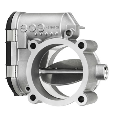
turbocharger applications...most are not designed for this. Bosch
Motorsport DV-E5 shown above and below.
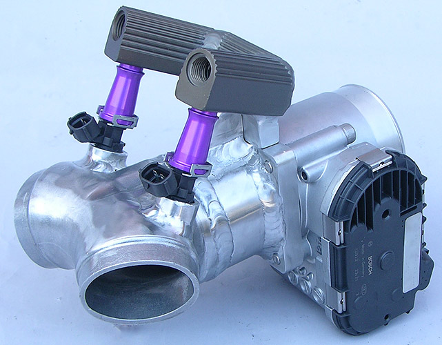
Here we have incorporated
a Bosch FBW 60mm throttle body to our 139 CID Harley Bonneville motor.
Two ID2000cc injectors are used for the turbocharged engine...all
controlled by the SQ6M.
Ultimate in
Programmable Control and Safety
Aircraft, like Stealth
Bombers and all modern airliners, use fly-by-wire technology where
programming and servo controls allow operation that would otherwise be
impossible. The same logic applies to motorsport where computer
controlled throttles can provide a competitive advantage in areas like
traction control and managing inlet flow in complex speed, rpm and load
intersects...all way beyond the capabilty of mechanical throttle
assemblies.
To get an idea of the complexity and to have a comprehensive look at
what it takes to calibrate a fly-by-wire, or throttle-by-wire system,
that involves Pedal Position Sensors (PPS) and Throttle Position
Sensors (TPS), Cosworth
has provided a 27 page document describing FBW setup procedure on
their MQ12 Engine Management Controllers.
A second Cosworth Pectel document outlines FBW Control Conditions.
SQ6M Fly By Wire
PPS/TPS Example
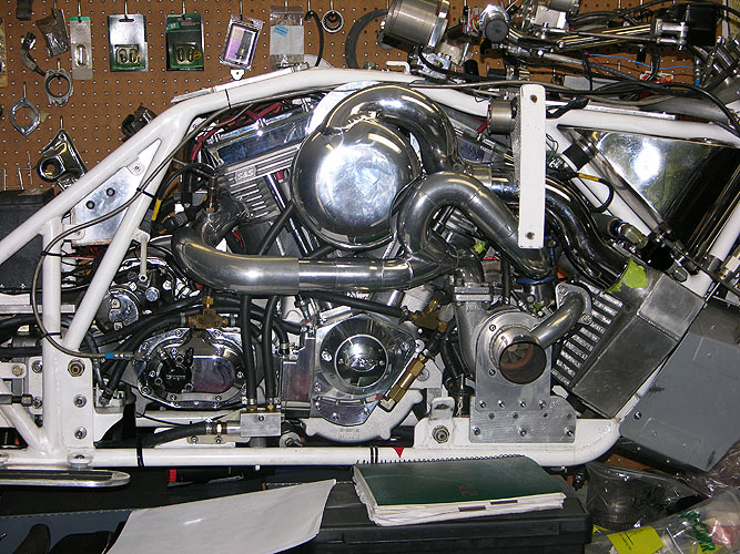
Not your typical race
vehicle for fly-by-wire control... A turbocharged 139 cubic inch
water-cooled and intercooled Harley-Davidson Bonneville racing
motorcycle. The Bonneville Bullett , at 1000 pounds, is no taller than your waist and geared for 294
mph. Be too aggressive with the throttle and things go wrong fast.
Turning 485 horsepower loose on the Bonneville Salt Flats on two wheels where
traction is a huge variable makes an excellent case for electronic
throttle control allowing for controlled throttle movement and boost by gear and
acting as important part of overall torque and traction control
management.
The below charts describe how we wire the PPS/TPS to the Pectel SQ6M on
this pushrod dinosaur.
TPS BOSCH 60mm DV-E5
BOSCH DV-E5
Throttle Body 0280750151
Pin #
|
BOSCH
FUNCTION
|
SQ6M CONNECTOR
PIN #
|
SQ6M FUNCTION
|
1
|
MOTOR -
|
C3-E
|
HB3B
|
2
|
POTI-
|
C2-1/C2-37
|
Analog Ground
|
3
|
POTI+
|
C2-16
|
OUT 5V
|
4
|
MOTOR+
|
C3-F
|
HB3A
|
5
|
POTI 2
|
C2-3
|
AIN8 (TPSA2)
|
6
|
POTI 1
|
C2-18
|
AIN7 (TPSA1)
|
PPS...Twist Grip to SQ6M
DEUTSCH DTM
PIN TO SOCKET
4 WAY CONNECTORS
Pin #
|
PPS
FUNCTION
|
SQ6M
PIN #
|
SQ6M
FUNCTION
|
1
|
VREF 5V
|
C2-16
|
OUT 5V
|
2
|
PPS1
|
C2-24
|
AIN9
|
3
|
PPS2
|
C2-8
|
AIN10
|
4
|
ANALOG
GROUND
|
C2-1/C2-37
|
Analog Ground
|
Both the TPS and the PPS
have 5VDc supplied by the Pectel SQ6M. Each also have dual,
counter-operating, potentiometers i.e. 0-5V and 5V to 0V with their
output voltages crossing at midway in their operation. These voltages
in the CalTool 3.6 software will correspond to a particular PPS and TPS
angle. The PPS gives it's inputs to the SQ6M not to the TPS. The SQ6M
takes these inputs and outputs a TPS movement based on all the TPS
programming parameters.
As there are different types of PPS and TPS hardware the SQ6M is
designed to operate with any variation. In our case, the Bosch DV-E5
TPS unit has a range of movement from 8 degrees forced shut to 90
degrees wide open and will generate opposing voltages for the two
potentiomenters TPSA1 and TPSA2 as it is opened and closed. In the "off
position" the TPS is held open by a strong spring at around 13 degrees
which is way too fast an idle setting for our application on our 2300cc
(139CID) engine.
Calibration involves PID programming as well as point by point, both in
the TPS and PPS, manually entering the degrees in the TPSA1/TPSA2 and
PPS1/PPS2 versus 17 voltage divisions with 2.5VDc at the midpoint.
"This should get you
running.. When you first switch on the ignition if the throttle
tries to open and has failure directly, (you will get warning alarms)
then reverse the motor direction either by changing the wiring pinout,
or by inverting it in the software under hardware setup/output setup,
h-bridge 3.
If the throttle
and PPS is set to LINEAR.. (I prefer to use USER_DEFINED), I have put a
close as
curve in (above). What to do?. First check the linear curves, set up
two
traces one PPS1 and PPS2 the other TPSA1 and TPSA2..
Open slowly the pedal then the throttle and
check that the curves are very close together and follow each other..
Write down the min and max degrees/percentages.. i.e. push the
butterfly
fully closed and check it is 8 degrees, then open to 90.. then change
to USER_DEFINED.. Push the throttle fully closed and set to the same as
linear
readings for TPSA1 (TPS above), and open and do the same.. I then
interpret the
points...Then use your eye and make the curve above and below minimum
point so the curve looks totally linear.. then go to TPSA2, now this
time, go to each voltage breakpoint and make the curve so the TPSA1 and
TPSA2 match perfectly. Do this for the full curve including max open
and fully closed, move through the range and check there is almost
a perfect match of the curves. Make sure you continue the linearization
of the curve above 90 and below 8 as you did in TPSA1. Then do the
same for PPS1 and PPS2 for 0 to 100. You will see that I have
"guessed" these, and you will see the way I have continued the curve..
If the throttle has difficulty opening reduce the FBW
control frequency, maybe to 2000hz but this shouldn't be needed.. i.e.
the
higher the hz the smoother and better the control, but the less power
to open the throttle.. but try these things below first...mostly
adjust the Proportional first.. if control is not good, set Integral
to 0 (zero) and get close as possible with Proportional, then fine tune with
Integral.. set up a time line chart with tps and tps aim on it so you
can see the function.. Note: Use as little Integral as possible, it can
cause transient problems when in operation that will not show when you
are setting up.. You may need to activate the Integral reset under
Output setup/FBW.
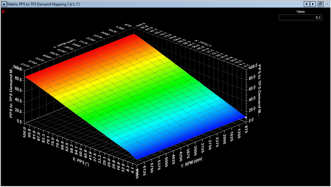
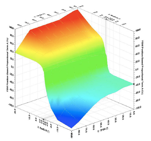
Throttle aim tables (above)found in Groups/STANDARD MAPPING/ BASE CALIBRATION 1-4...PPS
to TPS Demand Mapping Cal 1 to Cal 4: The PPS to TPS Aim Tables
have the PPS axis 0-100 and the Y axis your RPM range. These should be
linear graphs for PPS 0-100 values. Driving a
FBW throttle to the stops is a no no... results can be burnt motor,
broken drive gears and or stuck throttle.. Entries are degrees of the
TPS.
Autocal, don't bother with it, it is a pain in
the ass.. I use it if I have customer cars that I will not service or
some limited make championship, its not a simple throw some numbers at
it and let it autocal as some people think. The setup I gave it should
work, but only use it when all is setup perfect if you want to use it..
just need to enable it by sending the Dataset to the SQ6M."
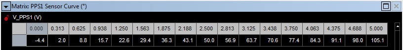
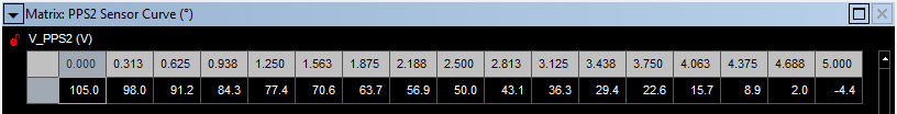
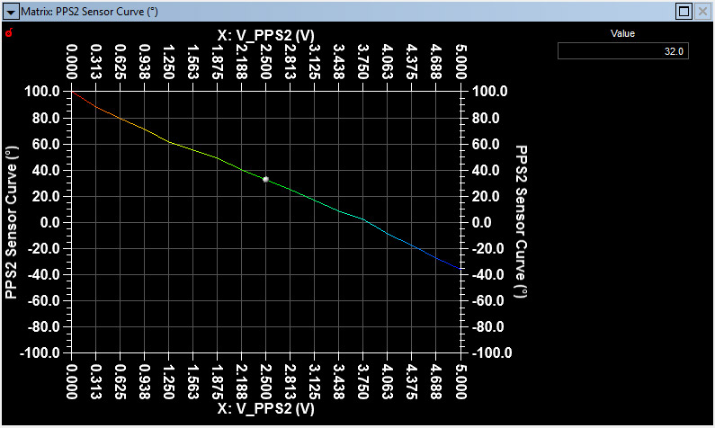
PPS/TPS Curve Examples (Matrix Surface Editor Charts)
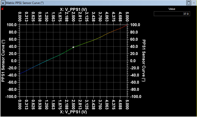
Here are the curves for
the PPS1 / PPS2 from our Bonneville Bullett that uses a Harley-Davidson
TBW twist grip (PPS) and a Bosch 60mm throttle body.
With the PPS resting shut enter zero degrees in the Matrix Editor where
the cursor is positioned....for both PPS1/PPS2. Then holding the PPS
wide open and do the same but enter 100 degrees. These two charts are
then interpolated between 0 and 100 degrees. Extend the
interpolations in a straight progression beyond both 0 and 100 degrees.
This is the starting point.
Slowly open the PPS. In the Matrix
Editor, edit the PPS1 and PPS2 so the degrees match each other as the
PPS is opened. If they are out of range the failure will be noted
in the Journal.
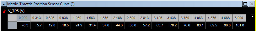
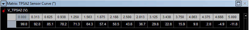
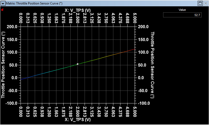
Here are the curves for the TPS and TPSA2 from our
Bonneville Bullett that uses a Harley-Davidson TBW twist grip and a
Bosch 60mm throttle body.
Pushing the TPS shut (after the 60 second TPS time out) enter 8
degrees in the Matrix Editor where the cursor is positioned....for both
TPS1 / TPS2. Then holding the TPS blade at 90 degrees do the same but
entering 90 degrees. Each of these two charts are then interpolated
between 8-90 degrees. This is the starting point.
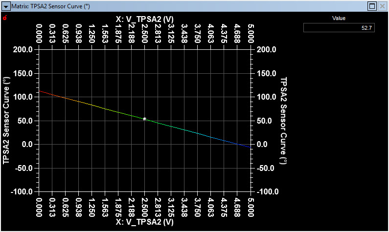
If the TPS has timed out slowly open the throttle blade (Never get your
finger in the TPS if it is powered up). In the Matrix Editor, edit the
TPS and TPSA2 so the degrees match each other as the butterfly is
opened. If they are out of range the failure will be noted in the
Journal.
If PPS1 and PPS2
accurately follow each other, and if TPS and TPSA2 accurately follow
each other, you can set the four PPS to TPS Demand Mapping matrices in Groups/STANDARD MAPPING/BASE CALIBRATION 1-4. You enter the target TPS degrees in the PPS v RPM matrix.
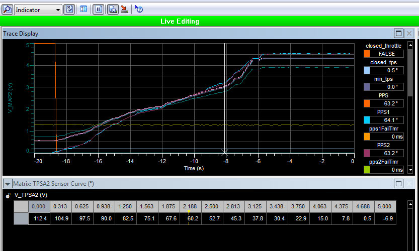
CalTool Trace Window
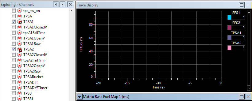
You can record your PPS
and TPS values by setting up a Trace Window in your Workspace. Click on
the blank Traces Window and then open the Exploring Channels by clicking
on the left arrow in the Exploring window...Then select your TPS/PPS
parameters from the myriad of categories. With the SQ6M powered up
slowly open the PPS and hit the Pause Button "II" at the top of the
page. You can now use the left/right arrow keys to scroll through your
recording and edit PPS1/PPS2 and TPSA1/TPSA2 entries. The sensor curves
will track your cursor movements with the yellow indicator.
In the example above we have PPS1 at 64.1 degrees and PPS2 at 63.2
degrees. These are close and if your out of bound failure degrees are
more than this (0.9 degrees) there will be no PPS failure at this
intersect. It's easy to edit and perfect the full range of all TPS and
PPS values. Very powerful.
167 FLY BY WIRE CATEGORIES
In CalTool 3.6 there are 167 categories to
either select, or fill in, in the Fly-By-Wire settings for the SQ6M to
control single or multiple Fly-By-Wire throttle bodies (TPS) as well as
different types of Pedal Position Sensors (PPS).
This level of detail, or complexity, is a logical approach that is
absolutely necessary for high level motorsport throttle control. We
have listed the 167 categories below. Within CalTool 3.6 each selection
has a dialog box with information on values, range, and editing options,
as well as a description in the form of a "balloon help window"
activated by a
mouseover.
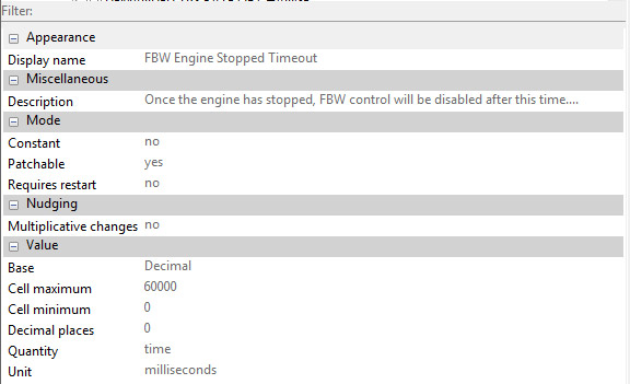
Example of the first grouping below
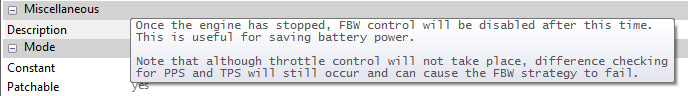
Groups / OUTPUT FUNCTIONS / FBW....Item 8 "FBW Engine Stopped Timeout (Ms)"
Details of selection in Dialog Box:
Mouseover Balloon Description
GREEN ENTRIES ARE FOR EXAMPLE ONLY
DETERMINE YOUR OWN ENTRIES
Groups / OUTPUT FUNCTIONS / FBW
1. FBW Enabled: ENABLED or DISABLED; ENABLED
2. FBW Control Frequency (Hz): 13 to 10000; 5000
3. FBW Control Minimum Duty (%): -100.0 to 100.0; -100.0
4. FBW Control Maximum Duty (%): -100 to 100; 100.0
5. TPS Target Limit Margin (Degrees): 0.0 to 200.0; 1.5
6. TPS Closed Value (Degrees): 0.0 to 200.0; 8.0
7. TPS Open Value (Degrees): 0.0 to 200.0; 90.0
8. FBW Engine Stopped Timeout (Ms): 0 to 60000; 60000
9. PID Integral Reset: ENABLED or DISABLED; DISABLED
Groups / OUTPUT FUNCTIONS / FBW / DEMANDED TPS RATE OF CHANGE
10. Demanded TPS Maximum Rate of Change: Angular velocity 0 to 1000 degrees per second; 7 x 2 Matrix
11. Demanded TPS Strategy Priority: Choice of three strategy
priorities in four categories to request a particular TPS position;
Groups / OUTPUT FUNCTIONS / FBW / DEMANDED TPS RATE OF CHANGE / TORQUE REDUCTION STRATEGY RATE LIMITS
12. FBW Method Selection By Source: Choice of three strategies in eight categories;
13. FBW Rate Limits: Matrix 9 x 3 of tps rising, falling, or exiting in eight categories;
Groups / OUTPUT FUNCTIONS / FBW / DEMANDED TPS RATE OF CHANGE / ALS STARTUP BLIP RATE LIMIT
14. ALS Startup FBW Blip Ramp-out Rate: Angular velocity 0.0 to 1000.0 degrees per second; 100.0
Groups / OUTPUT FUNCTIONS / FBW / DEMANDED TPS RATE OF CHANGE / CLOSED LOOP IDLE RATE LIMITS
15. Closed Loop Idle FBW Throttle Rate Limits: Angular velocity 0.0 to 1000.0 degrees per second; RISING 100.0; FALLING 100.0; EXITING 50.0
Groups / OUTPUT FUNCTIONS / FBW / PPS DIFFERENCE ERRORS
16. Maximum PPS Difference: Angle degrees 0.0 to 25.0; 5.0
17. PPS Failure Time: Seconds 0.00 to 1.00; 1.00
Groups / OUTPUT FUNCTIONS / FBW / TPS DIFFERENCE ERRORS
18. Maximum TPS Difference: Degrees 0.0 to 25.0; 7.0
19. TPS Failure Time: Seconds 0.00 to 1.00; 1.00
Groups / OUTPUT FUNCTIONS / FBW / TPS FEEDBACK ERRORS
20. FBW Error Margin: Degrees 0.0 to 100.0; 15.0
21. FBW Max Out-Of-Margin Time: 0 to 9999 Ms; 1000
Groups / OUTPUT FUNCTIONS / FBW / PPS NOISE ERRORS
22. PPS Error Decrement Rate: Degrees 0.0 to 100.0; 100.0
23. PPS Noise Threshold: Degseconds 0.0 to 40.0; 40.0
Groups / OUTPUT FUNCTIONS / FBW / TPS NOISE ERRORS
24. TPS Error Decrement Rate: Degrees 0.0 to 100.0; 100.0
25. TPS Noise Threshold: Degseconds 0.0 to 40.0; 40.0
Groups / OUTPUT FUNCTIONS / FBW / H-BRIDGE ERRORS
26. Half Bridge and PWM Temperature Maximum Threshold: -100 to 6453.5 Centigrade; 125.0
27. Half Bridge and PWM Temperature Error Time: Seconds 0.00 to 655.35; 3.00
Groups / OUTPUT FUNCTIONS / FBW / VOLTAGE REGULATOR ERRORS
28. Regulated Exciation Voltage Error Test Enable: ENABLED or DISABLED; DISABLED
29. Regulated Exciation Voltage Error Time: Seconds 0.00 to 655.35; 0.10
Groups / OUTPUT FUNCTIONS / FBW / AUTO-CALIBRATION (see Mick Kehl's comments above)
30. Auto-Cal Enable: ENABLED or DISABLED; DISABLED
31. Auto-Cal Trigger: Hex 0 h to ff h; 0 h
32. Auto-Cal Closed Duty: Percentage -100.0 to 100.0; -45.0
33. Auto-Cal Open Duty: Percentage -100.0 to 100.0; 80.0
34. Auto-Cal Open Time: Seconds 0.00 to 30.00; 1.00
35. Auto-Cal Close Time: Seconds 0.00 to 30.00; 1.00
36. Auto-Cal PPS1 Angle at Minimum Voltage: Degrees -200.0 to 120.0; 0.0
37. Auto-Cal PPS1 Angle at Maximum Voltage: Degrees -200.0 to 120.0; 100.0
38. Auto-Cal PPS2 Angle at Minimum Voltage: Degrees -200.0 to 120.0; 100.0
39. Auto-Cal PPS2 Angle at Maximum Voltage: Degrees -200.0 to 120.0; 0.0
40. TPS Closed Value: Degrees 0.0 to 200.0; 8.0
41. TPS Open Value: Degrees 0.0 to 200.0; 90.0
Groups / OUTPUT FUNCTIONS / FBW / AUTO-CALIBRATION / RANGE CHECKING
42. Auto-Cal Maximum Curve Difference: Degrees 0.0 to 10.0; 10.0
43. Auto-Cal PPS1 Maximum Low Voltage: Volts 0.000 to 5.000; 0.491
44. Auto-Cal PPS1 Minimum High Voltage: Volts 0.000 to 5.000; 4.465
45. Auto-Cal PPS2 Maximum Low Voltage: Volts 0.000 to 5.000; 0.490
46. Auto-Cal PPS2 Minimum High Voltage: Volts 0.000 to 5.000; 4.465
47. Auto-Cal TPSx1 Maximum Low Voltage: Volts 0.000 to 5.000; 0.812
48. Auto-Cal TPSx1 Minimum High Voltage: Volts 0.000 to 5.000; 4.167
49. Auto-Cal TPSx2 Maximum Low Voltage: Volts 0.000 to 5.000; 0.684
50. Auto-Cal TPSx2 Minimum High Voltage: Volts 0.000 to 5.000; 4.297
Groups / OUTPUT FUNCTIONS / FBW / AUTO-CALIBRATION / SERIAL DASH DIAGNOSTICS
51. Auto-Cal Serial Dash Codes: Three choices; 100_RPM_INC
Groups / OUTPUT FUNCTIONS / FBW / FAILURE ACTION
52. FBW Kill Engine on Fail: ENABLED or DISABLED; DISABLED
53. FBW Rev Cut on Fail: RPM 0 to 20000; 6500
54. FBW Rev Cut Reinstate on Fail: RPM 6500 to -13000; 5500
55. FBW Shutdown Ramp Enable: ENABLED or DISABLED; ENABLED
Groups / OUTPUT FUNCTIONS / FBW / PID SETTINGS
56. FBW PID Mode: LEGACY or ADVANCED; LEGACY
Groups / OUTPUT FUNCTIONS / FBW / PID SETTINGS / LEGACY PID MODE / PID A SETTINGS
57. FBW Integral Minimum A: Percent -100.0 to 0.0; -100.0
58. FBW Integral Maximum A: Percent 0.0 to 100.0; 100.0
59. FBW Proportional Term A: Entry in % -100.0 to 100.0 v. 33 divisions, Error -25 to 25 Degrees;
60. FBW Integral Gain A: Entry in % -100.0 to 100.0 v. 33 divisions, Error -25 to 25 Degrees;
61. FBW Derivative Term A: Entry in % -100.0 to 100.0 v. 33 divisions, Error -25 to 25 Degrees;
62. FBW Control Offset A: Percent -100.0 to 100.0 v. 9 divisions TPSA Degrees 1.0 to 91.0
Groups / OUTPUT FUNCTIONS / FBW / PID SETTINGS / LEGACY PID MODE / PID B SETTINGS
63. FBW Integral Minimum B: Percent -100.0 to 0.0; -100.0
64. FBW Integral Maximum B: Percent 0.0 to 100.0; 100.0
65. FBW Proportional Term B: Entry in % -100.0 to 100.0 v. 33 divisions, Error -25 to 25 Degrees;
66. FBW Integral Gain B: Entry in % -100.0 to 100.0 v. 33 divisions, Error -25 to 25 Degrees;
67. FBW Derivative Term B: Entry in % -100.0 to 100.0 v. 33 divisions, Error -25 to 25 Degrees;
68. FBW Control Offset B: Percent -100.0 to 100.0 v. 9 divisions TPSA Degrees 1.0 to 91.0
Groups / OUTPUT FUNCTIONS / FBW / PID SETTINGS / ADVANCED PID MODE / PID A SETTINGS
69. FBW Integral Minimum A: Percent -100.0 to 0.0; -100.0
70. FBW Integral Maximum A: Percent 0.0 to 100.0; 100.0
71. FBW Position Based Proportional Term A: Matrix 10 (TPSA Deg) x 17 (FBW ErrA -100 to 100 degrees)
72. FBW Integral Gain A: 17 entries (-100 to 100 ) x 17 (FBW ErrA -100 to 100 degrees)
73. FBW Derivative Term A: 17 Entries in % -100.0 to 100.0 v. FBWDelta ErrA -10 to 10 Degrees.
74. FBW Derivative Delta Period A: 1 to 0 Ms; 10
Groups / OUTPUT FUNCTIONS / FBW / PID SETTINGS / ADVANCED PID MODE / PID B SETTINGS
75. FBW Integral Minimum B: Percent -100.0 to 0.0; -100.0
76. FBW Integral Maximum B: Percent 0.0 to 100.0; 100.0
77. FBW Position Based Proportional Term B: Matrix 10 (TPSA Deg) x 17 (FBW ErrA -100 to 100 degrees)
78. FBW Integral Gain B: 17 entries (-100 to 100 ) x 17 (FBW ErrA -100 to 100 degrees)
79. FBW Derivative Term B: 17 Entries in % -100.0 to 100.0 v. FBWDelta ErrA -10 to 10 Degrees.
80. FBW Derivative Delta Period B: 1 to 0 Ms; 10
Groups / OUTPUT FUNCTIONS / FBW / PART-RANGE THROTTLE / TPS A
81. TPS A Part-Range Throttle Enable: ENABLED or DISABLED; DISABLED
82. TPS A Part-Range Threshold Angle: Degrees 0.0 to 200.0; 60.0
83. TPS A Part-Range Headroom Angle: Degrees 0.0 to 200.0; 2.0
Groups / OUTPUT FUNCTIONS / FBW / PART-RANGE THROTTLE / TPS B
84. TPS B Part-Range Throttle Enable: ENABLED or DISABLED; DISABLED
85. TPS B Part-Range Threshold Angle: Degrees 0.0 to 200.0; 60.0
86. TPS B Part-Range Headroom Angle: Degrees 0.0 to 200.0; 2.0
Groups / OUTPUT FUNCTIONS / FBW / FBW PWM OUT
87. FBW Output Function PWM Frequency: Hz 13 to 300; 50
88. FBW Output Function Service Time (Ms): 0 to 655350; 100
Groups / ANALOG SENSOR SETUP / CONTROL SENSORS / PEDAL POSITION SENSOR (PPS)
89. Pedal Position Sensors Input Select: ANALOG_INPUT or R2_INPUT; ANALOG_INPUT
Groups / ANALOG SENSOR SETUP / CONTROL SENSORS / PEDAL POSITION SENSOR (PPS) / PPS1 SENSOR
90. PPS1 Sensor Type: 4 Choices; USER_DEFINED
91. PPS1 Sensor Curve: 17 entries in degrees v. 17 equal divisions of 0-5VDc;
92. Minimum PPS1 Position (degrees): Degrees 0.0 to 200.0; 0.0
93. Maximum PPS1 Position (degrees): Degrees 0.0 to 200.0; 120.0
94. Minimum PPS1 Voltage: Volts 0.000 to 5.000; 0.021
95. Maximum PPS1 Voltage: Volts 0.000 to 5.000; 4.935
96. Failed PPS1 Position (degrees): Degrees 0.0 to 200.0; 2.0
97. PPS1 Failure Time: Ms 0 to 1000; 1000
Groups / ANALOG SENSOR SETUP / CONTROL SENSORS / PEDAL POSITION SENSOR (PPS) / PPS1 SENSOR/ PPS1 LINEAR POT SETUP
98. PPS1 Voltage 1: Volts 0.000 to 5.000; 0.256
99. PPS1 Position 1: Degrees -200.0 to 120.0; 0.0
100. PPS1 Voltage 2: Volts 0.000 to 5.000; 4.700
101. PPS1 Position 2: Degrees -200.0 to 120.0; 100.0
Groups / ANALOG SENSOR SETUP / CONTROL SENSORS / PEDAL POSITION SENSOR (PPS) / PPS2 SENSOR
102. PPS2 Sensor Type; 4 Choices; USER_DEFINED
103. PPS2 Sensor Curve: 17 entries in degrees v. 17 equal divisions of 0-5VDc
104. Minimum PPS2 Position (degrees): Degrees 0.0 to 200.0; 0.0
105. Maximum PPS2 Position (degrees): Degrees 0.0 to 200.0; 120.0
106. Minimum PPS2 Voltage: Volts 0.000 to 5.000; 0.020
107. Maximum PPS2 Voltage; Volts 0.000 to 5.000; 4.935
108. Failed PPS2 Position (degrees): Degrees 0.0 to 200.0; 2.0
109. PPS2 Failure Time: Ms 0 to 1000; 1000
Groups / ANALOG SENSOR SETUP / CONTROL SENSORS / PEDAL POSITION SENSOR (PPS) / PPS2 SENSOR/ PPS2 LINEAR POT SETUP
110. PPS2 Voltage 1: Volts 0.000 to 5.000; 4.700
111. PPS2 Position 1: Degrees -200.0 to 120.0; 0.0
112. PPS2 Voltage 2: Volts 0.000 to 5.000; 0.254
113. PPS2 Position 2: Degrees -200.0 to 120.0; 100.0
Groups / ANALOG SENSOR SETUP / CONTROL SENSORS / THROTTLE POSITION SENSOR (TPS) / TPSA1 SENSOR
114. Throttle Position Type: 4 Choices; USER_DEFINED
115. Throttle Position Software Filter: 100.0 to 0: 0.0
116. Throttle Position Sensor Curve: 17 entries in degrees v. 17 equal divisions of 0-5VDc
117. Throttle Position Sample Rate: Hz; 200
118. Minimum Throttle Position: Degrees 0.0 to 200.0; 0.0
119. Maximum Throttle Position: Degrees 0.0 to 200.0; 105.0
120. Minimum Throttle Voltage: Volts 0.000 to 5.000; 0.184
121. Maximum Throttle Voltage: Volts 0.000 to 5.000; 4.796
122. Failed Throttle Position: Degrees 0.0 to 200.0; 14.0
123. TPSA1 Faliure Time: Ms 0 to 1000; 1000
Groups / ANALOG SENSOR SETUP / CONTROL SENSORS / THROTTLE POSITION SENSOR (TPS) / TPSA1 SENSOR / TPSA1 LINEAR POT SETUP
124. TPSA1 Voltage 1: Volts 0.000 to 5.000; 0.498
125. TPSA1 Position 1: Degrees -200.0 to 120.0; 8.0
126. TPSA1 Voltage 2: Volts 0.000 to 5.000; 4.482
127. TPSA1 Position 2: Degrees -200.0 to 120.0; 90.0
Groups / ANALOG SENSOR SETUP / CONTROL SENSORS / THROTTLE POSITION SENSOR (TPS) / TPSA2 SENSOR
128. Throttle Position Type: 4 Choices; USER_DEFINED
129. Throttle Position Sensor Curve: 17 entries in degrees v. 17 equal divisions of 0-5VDc
130. Minimum TPSA2 Position: Degrees 0.0 to 200.0; 0.0
131. Maximum TPSA2 Position: Degrees 0.0 to 200.0; 105.0
132. Minimum TPSA2 Voltage: Volts 0.000 to 5.000; 0.038
133. Maximum TPSA2 Voltage: Volts 0.000 to 5.000; 4.493
134. Failed TPSA2 Position: Degrees 0.0 to 200.0; 14.0
135. TPSA2 Failure Time: Ms 0 to 1000; 1000
Groups / ANALOG SENSOR SETUP / CONTROL SENSORS / THROTTLE POSITION SENSOR (TPS) / TPSA2 SENSOR / TPSA2 LINEAR POT SETUP
136. TPSA2 Voltage 1: Volts 0.000 to 5.000; 4.620
137. TPSA2 Position 1: Degrees -200.0 to 120.0; 8.0
138. TPSA2 Voltage 2: Volts 0.000 to 5.000; 0.361
139. TPSA2 Position 2: Degrees -200.0 to 120.0; 90.0
Groups / ANALOG SENSOR SETUP / CONTROL SENSORS / THROTTLE POSITION SENSOR (TPS) / TPSB1 SENSOR
140. Throttle Position Type: 4 Choices; USER_DEFINED
141. Throttle Position Sensor Curve: 17 entries in degrees v. 17 equal divisions of 0-5VDc
142. Minimum TPSB1 Position: Degrees 0.0 to 200.0; 0.0
143. Maximum TPSB1 Position: Degrees 0.0 to 200.0; 100.0
144. Minimum TPSB1 Voltage: Volts 0.000 to 5.000; 0.000
145. Maximum TPSB1 Voltage: Volts 0.000 to 5.000; 5.000
146. Failed TPSB1 Position: Degrees 0.0 to 200.0; 0.0
147. TPSB1 Failure Time: Ms 0 to 1000; 1000
Groups / ANALOG SENSOR SETUP / CONTROL SENSORS / THROTTLE POSITION SENSOR (TPS) / TPSB1 SENSOR / TPSB1 LINEAR POT SETUP
148. TPSB1 Voltage 1: Volts 0.000 to 5.000; 0.000
149. TPSB1 Position 1: Degrees -200.0 to 120.0; 0.0
150. TPSB1 Voltage 2: Volts 0.000 to 5.000; 0.000
151. TPSB1 Position 2: Degrees -200.0 to 120.0; 0.0
Groups / ANALOG SENSOR SETUP / CONTROL SENSORS / THROTTLE POSITION SENSOR (TPS) / TPSB2 SENSOR
152. Throttle Position Type: 4 Choices; USER_DEFINED
153. TPSB2 Sensor Curve: 17 entries in degrees v. 17 equal divisions of 0-5VDc
154. Minimum TPSB2 Position: Degrees 0.0 to 200.0; 0.0
155. Maximum TPSB2 Position: Degrees 0.0 to 200.0; 100.0
156. Minimum TPSB2 Voltage: Volts 0.000 to 5.000; 0.000
157. Maximum TPSB2 Voltage: Volts 0.000 to 5.000; 5.000
158. Failed TPSB2 Position: Degrees 0.0 to 200.0; 0.0
159. TPSB2 Failure Time: Ms 0 to 1000; 1000
Groups / ANALOG SENSOR SETUP / CONTROL SENSORS / THROTTLE POSITION SENSOR (TPS) / TPSB2 SENSOR / TPSB2 LINEAR POT SETUP
160. TPSB2 Voltage 1: Volts 0.000 to 5.000; 0.000
161. TPSB2 Position 1: Degrees -200.0 to 120.0; 0.0
162. TPSB2 Voltage 2: Volts 0.000 to 5.000; 0.000
163. TPSB2 Position 2: Degrees -200.0 to 120.0; 0.0
Groups / STANDARD MAPPING / BASE CALIBRATION / PPS to TPS Demand Mapping Cal (1-4)
164. Cal 1: TPS Degrees 0.0 to 100.0: Matrix 15 RPM Sites x 25 PPS Sites (0 to 100 Degrees)
165. Cal 2: TPS Degrees 0.0 to 100.0: Matrix 15 RPM Sites x 25 PPS Sites (0 to 100 Degrees)
166. Cal 3: TPS Degrees 0.0 to 100.0: Matrix 15 RPM Sites x 25 PPS Sites (0 to 100 Degrees)
167. Cal 4: TPS Degrees 0.0 to 100.0: Matrix 15 RPM Sites x 25 PPS Sites (0 to 100 Degrees)