Advanced Engine Management: CalTool 3.6 Pectel SQ6M, Fuel
Modifiers


Fuel Prediction

In that there are four
Fuel Maps in CalTool and each can be up to 25 RPM sites by 25
Load sites (625) entries we try to automate the process a bit by
predicting the values in Excel. Here we have constructed a 25 x 25
Excel Spreadsheet that automatically generates the XX.XX millisecond
values based on injector size, fuel pressure, compressor maps,
horsepower and other factors. It provides a starting point that will
get the application running right away with no danger of being too lean
under boost.
This is a sequential fire example. The spreadsheet also predicts batch
fire fuel maps. Up to five keystrokes xx.xx times four 625 matrices
takes a lot of time.
Fuel Maps and Fuel
Modifiers
Groups/STANDARD MAPPING/BASE CALIBRATION
(1-4)
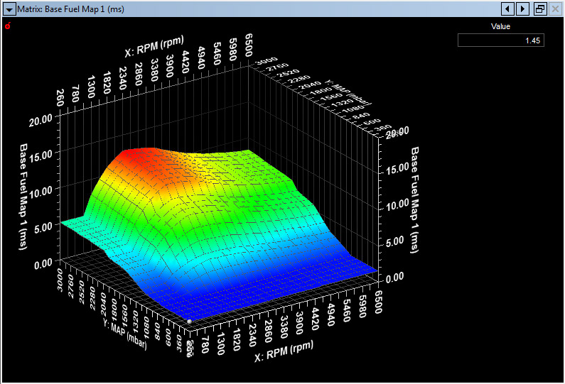
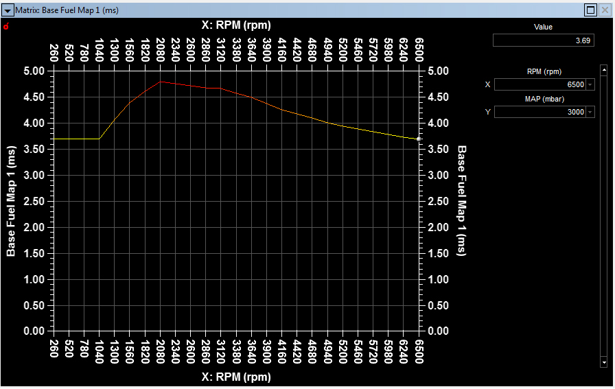
Fuel Maps in CalTool 3.6 can
have up to 50 RPM sites and 25 Load Sites. In the picture above we have
set up
a 25 x 25 fuel map for 3 Bar and 6500 RPM operation. A unique feature
of CalTool 3.6 is that the RPM axis does not have to be equally spaced
i.e. if you need increased resolution in a certain rpm range you can do
so. There are four (4) base calibrations in the SQ6M engine controller.
The user can switch these "on the fly" with a Cal-Pot rotary switch.
You can edit in either the
3D "Matrix Surface Editor" shown above or on in a 2D "Matrix Editor"
table format shown below.
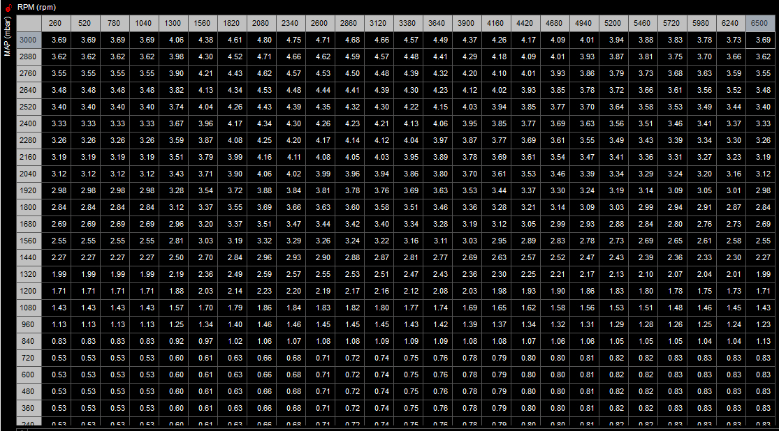
Editing is done in a
number of ways, either by direct one cell edit, by the entire map, or
selected areas. Math functions are available for editing. Basic
resolution is .01 millisecond or .00001 seconds. Any finer gradation
than this is meaningless. We generate our four
base maps in Excel using predictive equations to save time...If you
have four spark maps and four fuel maps and they are maxed out at 50
RPM x 25 Load sites that is up to 40,000 digits and 10,000 decimal
points you get to manually enter. We automate the process and use copy
and paste from Excel to CalTool 3.6.
In either format you use the arrow keys to navigate about
the map. In the 3D format you use the CTRL Key and the arrow keys to
rotate or flip the map.
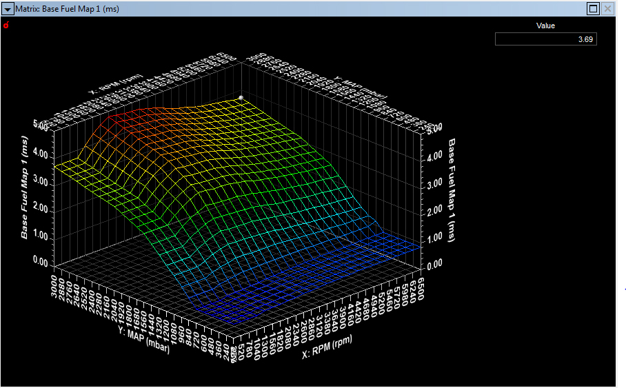
When in the Matrix Surface
Editor mode (top image) if you "right click" your map, a dialog
box will pop up and in "View" you have a number of ways to view your
fuel map data. Pictured above is a Wireframe view.
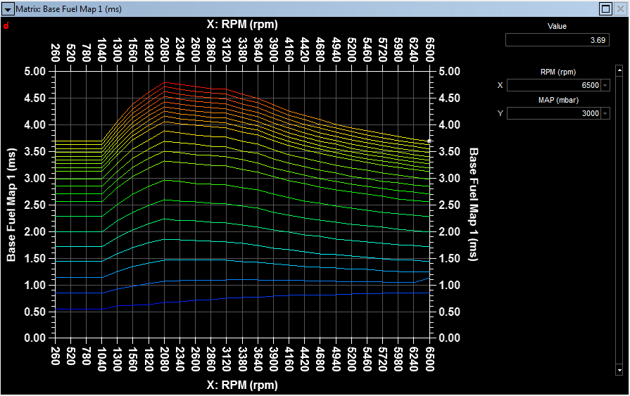
Above is the X Axis Slice. This is very useful, especially in Turbo maps to look for mistakes in manual editing.
Here we are looking at a Single X Slice. Wherever you have left the cursor that X Axis row will be displayed.
CalTool 3.6 Fuel
Modifiers
Beyond the basic four fuel maps there are about 75 programmable
modifiers for the final injection event. The level of detail is of
professional motorsport requirement and way beyond lesser engine
management systems.
Groups / STANDARD MAPPING / FUEL CORRECTIONS
1. Injection Angle
Control Method: END_ANGLE or START ANGLE
2. Injection Angle Rate of
Change (deg/Cylinder): 0.25 to 719.75
3. Base Cal Select Enable: ENABLED
or DISABLED
Groups
/ STANDARD MAPPING / FUEL CORRECTIONS / MULTIPLIERS / THROTTLE
MULTIPLIERS
4. Throttle Multiplier: Correction
for TPS Angle; Matrix of TPS degrees v. RPM
5. Enable Fuel Map Multimaps: ENABLED
or DISABLED;
If disabled a matrix of RPM v TPS degrees modifies the base fuel map
from 0 to 200% i.e. an entry of 1.00 means no correction. If
enabled six (6) multipmaps with matrices of RPM v MAP are activated,
also 0 to 200%.
Groups / STANDARD MAPPING / FUEL
CORRECTIONS / MULTIPLIERS / ENGINE COOLANT MULTIPLIERS / SINGLE
CALIBRATION
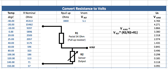
Sensor Data is often given in resistance v. temperature.
Use this calculator (Excel Spreadsheet) when using 3K pullup resistor for temperature calibration.
Groups / STANDARD MAPPING / FUEL CORRECTIONS / MULTIPLIERS
7. Air Charge Temperature Multiplier
8. Ambient Air Temperature Multiplier
9. Atmospheric Pressure Multiplier
10. Engine Oil Pressure Multiplier
11. Engine Oil Temperature Multiplier
12. Exhaust Temperatrure Correction
13. Fuel Pressure Multiplier
14. Fuel Temperature Multiplier
15. Global Fuel Multiplier
16. 360 Sync Multiplier
Groups / STANDARD MAPPING / FUEL CORRECTIONS / ADDERS
17. Battery Adder
Groups / STANDARD MAPPING / FUEL CORRECTIONS / CLOSED LOOP LAMBDA
18. Closed Loop Lambda Update Rate
19. Lambda Correction Minimum
20. Lambda Correction Maximum
21. Closed Loop Lambda Target Exhaust Temperature Correction
22. Closed Loop Lambda Target Multiplier f(ECT)
Groups / STANDARD MAPPING / FUEL CORRECTIONS / CLOSED LOOP LAMBDA /
ENABLE/DISABLE
23. Closed Loop Lambda Enable: ENABLED or DISABLED
24. Lambda Correction Minimum
25. Lambda Correction Maximum
Groups / STANDARD MAPPING / FUEL CORRECTIONS / CLOSED LOOP LAMBDA / PID
PARAMETERS / SIMPLE LAMBDA
26. Simple Lambda Rich Lambda Error
27. Simple Lambda Lean Lambda Error
Groups / STANDARD MAPPING / FUEL CORRECTIONS / CLOSED LOOP LAMBDA / PID
PARAMETERS
28. Closed Loop Lambda Proportional
Gain
29. Closed loop Lambda Integral Gain
30. Integral Total Minimum
31. Integral Total Maximum
Groups / STANDARD MAPPING / FUEL CORRECTIONS / CLOSED LOOP LAMBDA /
DISABLE TIMERS
32. Closed Loop Disable Time Sensor
Warmup
33. Closed Loop
Disable Time Starting
34. Closed
Loop Disable Time During Fuel Cut
35. Closed Loop
Disable Time During Transient
36. Closed Loop
Disable Time During Gear Shift
Groups / STANDARD MAPPING / FUEL CORRECTIONS / CLOSED LOOP LAMBDA /
CATALYST ADJUSTMENT
37. Lambda Target Adjust disable
f(RPM)
38. Lambda Target
Adjust enable f(RPM)
39. Lambda Target
Adjust disable f(TPS)
40. Lambda Target
Adjust enable f(TPS)
41. Lambda Target
Adjustment
Groups / STANDARD MAPPING / FUEL CORRECTIONS / OVERRUN FUELING
42. Overrun Fuel Cut Off Cal (1-4
Maps): RPM entries f(ECT)
43. Overrun Fuel Reinstate Cal (1-4
Maps): RPM entries f(ECT)
Groups / STANDARD MAPPING / FUEL CORRECTIONS / FUELING DURING STARTING
44. Injection Start Angle in Crank
Groups / STANDARD MAPPING / FUEL CORRECTIONS / FUELING DURING STARTING
/ SINGLE CALIBRATIONS
45. Preliminary Injection: Ms v.
ECT: Wets manifold walls at start event
46. Base Fuel in Crank: Ms v. TPS: Base value during cranking
47. Cranking Multiplier: Matrix ECT v. Cranking engine turns
Groups / STANDARD MAPPING / FUEL CORRECTIONS / BANKED INJECTION /
SECONDARY INJECTOR LEAN LIMIT
48. Secondary Injector Lean Limit
Function Enable: ENABLED or DISABLED
49. Secondary
Injector Lean Limit Minimum Lambda
50. Secondary
Injector Lean Limit Minimum Throttle Angle
51. Secondary
Injector Lean Limit Minimum Engine Speed
52. Secondary
Injector Lean Limit Minimum Lambda Correction
53.
Secondary Injector Lean Limit Error Time
Groups / STANDARD MAPPING / FUEL CORRECTIONS / BANKED INJECTION
54.
Enable Banked Injection
55. Injector Bank Split
56. Injector Bank Split Rate of Change
57. Secondary Injector Bank Scale
58. Secondary Injector Bank Switch On Time
59. Secondary
Injector Bank Switch Off Time
60. Primary Bank Switch Off Time
61. Switch-over Multiplier
62. Switch-over Decay Multiplier
Groups / STANDARD MAPPING / FUEL CORRECTIONS / TRANSIENT FUEL CORRECTION
63. Maximum Engine Speed
64. Start Cylinder Count Before TFC
65. Enable Time Based Transients: ENABLED or DISABLED
66. Maximum Throttle Angle
67. Minimum Delta Throttle
68. Accel Positive Gain
69. Accel Positive Decay
70. Accel Positive Clamp
71. Accel Negative Gain
72. Accel Negative Decay
73. Accel Nggative Clamp
Groups / STANDARD MAPPING / FUEL CORRECTIONS / INDIVIDUAL CYLINDER TRIM
74. Enable Cylinder Fuel Trim: ENABLED or DISABLED
75. Cylinder (Cylinders
individually 1 to 12): MAP v. RPM